Search This Blog

Saturday, August 5, 2017

BSNL ADSL MODEM DSLW 200 NEW CONFIGURATION

Bsnl Broadband customers are facing problem now a days due to a virus attack on their modems. As stated by PTI around 2000 modems whose default password was not changed, are affected.
BSNL has been working to resolve this issue but still its customers are facing a huge problem.

Here I am providing the step by step procedure to resolve this issue. still if problem is not  resolved you can bsnl customer care executive.
This configuration is for modem model DSLW 200 which looks
 like this.


Follow these step now:

Step1: Reset your modem.
On the back side of the modern you can see a small reset pin hole. You have to press the button using a pin. Press it for at least 10 sec until the lights start to blink.

Step 2: Now you remove all the  cables except Ethernet wire (RJ45) connected to your computer and modem power cable.

Step3: on your computer you will see limited connection. Now open any browser and enter the address 192.168.1.1
this address will open your modem configuration but you will be required to enter login id and password.

login id: admin
password: admin 

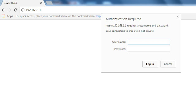
On successful login you will see this screen 


Step 4: In interface setup select internet  modify the settings of service name, username and password as shown in the image with arrow mark. Read below for service name and username creation.

In service name : dataone
In username : This is unique id and you need to create this using the details of your connection. There are 3 parts in password. for first part you will require the name of the connection owner i.e. on whose name connection is taken. The first two letters of the id is the first two letter of the owner name.
second part is the phone no with area code (removing first zero) e.g. if area code is 05228 and phone no is 222222 then fill 5228222222
third part is ncdr

Combining all these the username will be

<first two letter of owner>_<phone no with area code>_<ncdr>

save the setting as shown

Step 5: configure for wifi in wireless section  as shown in image
Modify accordingly the colouns marked with arrow.


Step6: In Access management setting activate the ACL


Step7: Now change the router password in maintenance and save the settings


Step8: restart the modem with current settings and make all cable connection.

if you still unable to configure, you can ask me in comment or get it reconfigured at your local exchange.

Monday, May 20, 2013

                                 Linux From Scratch

This blog is about the personal experience , I got while following the Linux From Scratch 7.3. I am using Fedora 16 on Intel x86_64 platform.

Since I have the basic knowledge  about Linux kernel compilation and use of simple commands, the first major task is to check the prerequisite packages. The script is: 
cat > version-check.sh << "EOF"
#!/bin/bash
# Simple script to list version numbers of critical development tools
export LC_ALL=C
bash --version | head -n1 | cut -d" " -f2-4
echo "/bin/sh -> `readlink -f /bin/sh`"
echo -n "Binutils: "; ld --version | head -n1 | cut -d" " -f3-
bison --version | head -n1
if [ -e /usr/bin/yacc ];
then echo "/usr/bin/yacc -> `readlink -f /usr/bin/yacc`";
else echo "yacc not found"; fi
bzip2 --version 2>&1 < /dev/null | head -n1 | cut -d" " -f1,6-
echo -n "Coreutils: "; chown --version | head -n1 | cut -d")" -f2
diff --version | head -n1
find --version | head -n1
gawk --version | head -n1
if [ -e /usr/bin/awk ];
then echo "/usr/bin/awk -> `readlink -f /usr/bin/awk`";
else echo "awk not found"; fi
gcc --version | head -n1
ldd --version | head -n1 | cut -d" " -f2- # glibc version
grep --version | head -n1
gzip --version | head -n1
cat /proc/version
m4 --version | head -n1
make --version | head -n1
patch --version | head -n1
echo Perl `perl -V:version`
sed --version | head -n1
tar --version | head -n1
echo "Texinfo: `makeinfo --version | head -n1`"
xz --version | head -n1
echo 'main(){}' > dummy.c && gcc -o dummy dummy.c
if [ -x dummy ]
then echo "gcc compilation OK";
else echo "gcc compilation failed"; fi
rm -f dummy.c dummy
EOF
bash version-check.sh


My host system didn't contain the bison package, so I installed it.You guys, check for it and then check /usr/bin for yacc  . If it is not present , then run the following command ( you must be super-user):

yum install flex bison 
yum install flex
yum install byacc

Check for link again..this solved my problem.

The wget-list is:
http://ftp.gnu.org/gnu/autoconf/autoconf-2.69.tar.xz
http://ftp.gnu.org/gnu/automake/automake-1.13.1.tar.xz
http://ftp.gnu.org/gnu/bash/bash-4.2.tar.gz
http://ftp.gnu.org/gnu/binutils/binutils-2.23.1.tar.bz2
http://ftp.gnu.org/gnu/bison/bison-2.7.tar.xz
http://www.bzip.org/1.0.6/bzip2-1.0.6.tar.gz
http://sourceforge.net/projects/check/files/check/0.9.9/check-0.9.9.tar.gz
http://ftp.gnu.org/gnu/coreutils/coreutils-8.21.tar.xz
http://ftp.gnu.org/gnu/dejagnu/dejagnu-1.5.tar.gz
http://ftp.gnu.org/gnu/diffutils/diffutils-3.2.tar.gz
http://prdownloads.sourceforge.net/e2fsprogs/e2fsprogs-1.42.7.tar.gz
http://prdownloads.sourceforge.net/expect/expect5.45.tar.gz
ftp://ftp.astron.com/pub/file/file-5.13.tar.gz
http://ftp.gnu.org/gnu/findutils/findutils-4.4.2.tar.gz
http://prdownloads.sourceforge.net/flex/flex-2.5.37.tar.bz2
http://ftp.gnu.org/gnu/gawk/gawk-4.0.2.tar.xz
http://ftp.gnu.org/gnu/gcc/gcc-4.7.2/gcc-4.7.2.tar.bz2
http://ftp.gnu.org/gnu/gdbm/gdbm-1.10.tar.gz
http://ftp.gnu.org/gnu/gettext/gettext-0.18.2.tar.gz
http://ftp.gnu.org/gnu/glibc/glibc-2.17.tar.xz
ftp://ftp.gmplib.org/pub/gmp-5.1.1/gmp-5.1.1.tar.xz
http://ftp.gnu.org/gnu/grep/grep-2.14.tar.xz
http://ftp.gnu.org/gnu/groff/groff-1.22.2.tar.gz
http://ftp.gnu.org/gnu/grub/grub-2.00.tar.xz
http://ftp.gnu.org/gnu/gzip/gzip-1.5.tar.xz
http://anduin.linuxfromscratch.org/sources/LFS/lfs-packages/conglomeration//iana-etc/iana-etc-2.30.tar.bz2
http://ftp.gnu.org/gnu/inetutils/inetutils-1.9.1.tar.gz
http://www.kernel.org/pub/linux/utils/net/iproute2/iproute2-3.8.0.tar.xz
http://ftp.altlinux.org/pub/people/legion/kbd/kbd-1.15.5.tar.gz
http://www.kernel.org/pub/linux/utils/kernel/kmod/kmod-12.tar.xz
http://www.greenwoodsoftware.com/less/less-451.tar.gz
http://www.linuxfromscratch.org/lfs/downloads/7.3/lfs-bootscripts-20130123.tar.bz2
http://download.savannah.gnu.org/releases/libpipeline/libpipeline-1.2.2.tar.gz
http://ftp.gnu.org/gnu/libtool/libtool-2.4.2.tar.gz
http://www.kernel.org/pub/linux/kernel/v3.x/linux-3.8.1.tar.xz
http://ftp.gnu.org/gnu/m4/m4-1.4.16.tar.bz2
http://ftp.gnu.org/gnu/make/make-3.82.tar.bz2
http://download.savannah.gnu.org/releases/man-db/man-db-2.6.3.tar.xz
http://www.kernel.org/pub/linux/docs/man-pages/man-pages-3.47.tar.xz
http://www.multiprecision.org/mpc/download/mpc-1.0.1.tar.gz
http://www.mpfr.org/mpfr-3.1.1/mpfr-3.1.1.tar.xz
ftp://ftp.gnu.org/gnu/ncurses/ncurses-5.9.tar.gz
http://ftp.gnu.org/gnu/patch/patch-2.7.1.tar.xz
http://www.cpan.org/src/5.0/perl-5.16.2.tar.bz2
http://pkgconfig.freedesktop.org/releases/pkg-config-0.28.tar.gz
http://sourceforge.net/projects/procps-ng/files/Production/procps-ng-3.3.6.tar.xz
http://prdownloads.sourceforge.net/psmisc/psmisc-22.20.tar.gz
http://ftp.gnu.org/gnu/readline/readline-6.2.tar.gz
http://ftp.gnu.org/gnu/sed/sed-4.2.2.tar.bz2
http://pkg-shadow.alioth.debian.org/releases/shadow-4.1.5.1.tar.bz2
http://www.infodrom.org/projects/sysklogd/download/sysklogd-1.5.tar.gz
http://download.savannah.gnu.org/releases/sysvinit/sysvinit-2.88dsf.tar.bz2
http://ftp.gnu.org/gnu/tar/tar-1.26.tar.bz2
http://prdownloads.sourceforge.net/tcl/tcl8.6.0-src.tar.gz
http://www.iana.org//time-zones/repository/releases/tzdata2012j.tar.gz
http://ftp.gnu.org/gnu/texinfo/texinfo-5.0.tar.xz
http://www.freedesktop.org/software/systemd/systemd-197.tar.xz
http://anduin.linuxfromscratch.org/sources/other/udev-lfs-197-2.tar.bz2
http://www.kernel.org/pub/linux/utils/util-linux/v2.22/util-linux-2.22.2.tar.xz
ftp://ftp.vim.org/pub/vim/unix/vim-7.3.tar.bz2
http://tukaani.org/xz/xz-5.0.4.tar.xz
http://www.zlib.net/zlib-1.2.7.tar.bz2
http://www.linuxfromscratch.org/patches/lfs/7.3/bash-4.2-fixes-11.patch
http://www.linuxfromscratch.org/patches/lfs/7.3/binutils-2.23.1-testsuite_fix-1.patch
http://www.linuxfromscratch.org/patches/lfs/7.3/bzip2-1.0.6-install_docs-1.patch
http://www.linuxfromscratch.org/patches/lfs/7.3/coreutils-8.21-i18n-1.patch
http://www.linuxfromscratch.org/patches/lfs/7.3/flex-2.5.37-bison-2.6.1-1.patch
http://www.linuxfromscratch.org/patches/lfs/7.3/kbd-1.15.5-backspace-1.patch
http://www.linuxfromscratch.org/patches/lfs/7.3/make-3.82-upstream_fixes-3.patch
http://www.linuxfromscratch.org/patches/lfs/7.3/perl-5.16.2-libc-1.patch
http://www.linuxfromscratch.org/patches/lfs/7.3/readline-6.2-fixes-1.patch 
 
save it at root(/) .
run the wget command from root(/).
 

Friday, September 28, 2012

Mail Ack Button

Most of the times it becomes important to know whether the receiver of our mail has read the mail or not. Mail Ack Button provides an addition feather, which can be selected by the owner of the email id which gives the receiver to send a acknowledge to the sender by clicking on the ack button.
This feature is fully optional and must be possess by both sides to use it.  

Saturday, May 5, 2012

lcd commands

No. InstructionHexDecimal
1 Function Set: 8-bit, 1 Line, 5x7 Dots 0x3048
2 Function Set: 8-bit, 2 Line, 5x7 Dots 0x3856
3 Function Set: 4-bit, 1 Line, 5x7 Dots 0x2032
4 Function Set: 4-bit, 2 Line, 5x7 Dots 0x2840
5Entry Mode0x066
6 Display off Cursor off
(clearing display without clearing DDRAM content)
0x088
7 Display on Cursor on 0x0E14
8 Display on Cursor off 0x0C12
9 Display on Cursor blinking 0x0F15
10 Shift entire display left 0x1824
12 Shift entire display right 0x1C30
13 Move cursor left by one character 0x10 16
14 Move cursor right by one character 0x1420
15 Clear Display (also clear DDRAM content)0x011
16 Set DDRAM address or coursor position on display 0x80+add* 128+add*
17 Set CGRAM address or set pointer to CGRAM location0x40+add**64+add**

Monday, April 2, 2012

EPP Explained


Interfacing the Enhanced Parallel Port

Table of Contents

Enhanced Parallel Port
EPP Hardware Properties
The EPP Handshake
EPP Data Write Cycle
EPP Address Write Cycle
EPP Data Read Cycle
EPP Address Read Cycle
The EPP's Software Registers
EPP Programming Considerations


EPP - Enhanced Parallel Port
    The Enhanced Parallel Port (EPP) was designed in a joint venture between Intel, Xircom & Zenith Data Systems. EPP Ports were first specified in the EPP 1.7 standard, and then later included in the IEEE 1284 Standard released in 1994. EPP has two standards, EPP 1.7 and EPP 1.9. There are differences between the two standards which may affect the operation of devices. This is further discussed latter. EPP has a typical transfer rate in the order of 500KB/S to 2MB/S. This is achieved by allowing the hardware contained in the port to generate handshaking, strobing etc, rather that have the software do it, which was the case with Centronics. For the hobbyist, EPP is more commonly used than ECP. EPP differs from ECP by the fact that the EPP Port generates and controls all the transfers to and from the peripheral. ECP on the other hand requires the peripheral to negotiate a reverse channel and control the handshaking. This is harder to achieve with common glue logic, thus really requires a dedicated controller or ECP Peripheral Chip.
EPP Hardware Properties
    When using EPP mode, a different set of tasks and labels are assigned to each line. These are listed below in Table 4. It's very common to see both the SPP and EPP names interchanged in Parallel Port Data Sheets and Literature. This can make it very hard to focus on what is exactly happening. Therefore all the documentation here will use the EPP names.
    Pin
    SPP Signal
    EPP Signal
    IN/OUT
    Function
    1
    Strobe
    Write
    Out
    A low on this line indicates a Write, High indicates a Read
    2-9
    Data 0-7
    Data 0-7
    In-Out
    Data Bus. Bi-directional
    10
    Ack
    Interrupt
    In
    Interrupt Line. Interrupt occurs on Positive (Rising) Edge.
    11
    Busy
    Wait
    In
    Used for handshaking. A EPP cycle can be started when low, and finished when high.
    12
    Paper Out / End
    Spare
    In
    Spare - Not Used in EPP Handshake
    13
    Select
    Spare
    In
    Spare - Not Used in EPP Handshake
    14
    Auto Linefeed
    Data Strobe
    Out
    When Low, indicates Data transfer
    15
    Error / Fault
    Spare
    In
    Spare - Not used in EPP Handshake
    16
    Initialize
    Reset
    Out
    Reset - Active Low
    17
    Select Printer
    Address Strobe
    Out
    When low, indicates Address transfer
    18-25
    Ground
    Ground
    GND
    Ground
    Table 1. Pin Assignments For Enhanced Parallel Port Connector.
    Paper Out, Select and Error are not defined in the EPP handshake. These lines can be utilised in any way by the user. The status of these lines can be determined at anytime by viewing the SPP Status Register. Unfortunately there are no spare output's. This can become a hassle regularly.
The EPP Handshake
    In order to perform a valid exchange of data using EPP we must follow the EPP handshake. As the hardware does all the work, this handshake only requires to be used for your hardware and not for software as the case with SPP. To initiate an EPP cycle your software needs to perform only one I/O operation to the relevant EPP Register. Details on this, latter. EPP Data Write Cycle
    Enhanced Parallel Port Data Write Cycle
    Figure 1. Enhanced Parallel Port Data Write Cycle.
    1. Program writes to EPP Data Register. (Base + 4) 2. nWrite is placed low. (Low indicates write operation)
    3. Data is placed on Data Lines 0-7. 4. nData Strobe is asserted if Wait is Low (O.K. to start cycle)
    5. Host waits for Acknowledgment by nWait going high (O.K. to end cycle) 6. nData Strobe is de-asserted.
    7. EPP Data Write Cycle Ends.
    EPP Address Write Cycle
    Enhanced Parallel Port Address Write Cycle
    Figure 2. Enhanced Parallel Port Address Write Cycle.
    1. Program writes address to EPP's Address Register (Base + 3) 2. Write is placed low. (Low indicates write operation)
    3. Address is placed on Data Lines 0-7. 4. Address Strobe is asserted if Wait is Low (O.K. to start cycle)
    5. Host waits for Acknowledgment by wait going high (O.K. to end cycle) 6. nAddress Strobe is De-asserted.
    7. EPP Address Write Cycle Ends.
    EPP Data Read Cycle
    Enhanced Parallel Port Data Read Cycle
    Figure 3. Enhanced Parallel Port Data Read Cycle.
    1. Program reads EPP Data Register. (Base + 4) 2. nData Strobe is asserted if Wait is Low (O.K. to start cycle)
    3. Host waits for Acknowledgment by nWait going high 4. Data is read from Parallel Port Pins.
    5. nData Strobe is de-asserted. 6. EPP Data Read Cycle Ends.
    EPP Address Read Cycle
    Enhanced Parallel Port Address Read Cycle
    Figure 4. Enhanced Parallel Port Address Read Cycle.
    1. Program reads EPP Address Register. (Base + 3) 2. nAddr Strobe is asserted if Wait is Low (O.K. to start cycle)
    3. Host waits for Acknowledgment by nWait going high 4. Data is read from Parallel Port Pins.
    5. nAddr Strobe is de-asserted. 6. EPP Address Read Cycle Ends.
    Note If implementing EPP 1.7 Handshake (Pre IEEE 1284) the Data and Address Strobes can be asserted to start a cycle regardless of the wait state. EPP 1.9 will only start a cycle once wait is low. Both EPP 1.7 and EPP 1.9 require the wait to be high to finish a cycle.
The EPP's Software Registers.
    The EPP Port also has a new set of registers. However 3 of them have been inherited from the Standard Parallel Port. Below is a table showing the new and existing registers.
    Address
    Port Name
    Read/Write
    Base + 0
    Data Port (SPP)
    Write
    Base + 1
    Status Port (SPP)
    Read
    Base + 2
    Control Port (SPP)
    Write
    Base + 3
    Address Port (EPP)
    Read/Write
    Base + 4
    Data Port (EPP)
    Read/Write
    Base + 5
    Undefined (16/32bit Transfers)
    -
    Base + 6
    Undefined (32bit Transfers)
    -
    Base + 7
    Undefined (32bit Transfers)
    -
    Table 2 EPP Registers
    As you can see, the first 3 addresses are exactly the same than the Standard Parallel Port Register and behave in exactly the same way. Therefore if you used a Enhanced Parallel Port, you can output data to Base + 0 in exactly the same fashion than you would if it was a Standard Parallel Port (SPP). If you were to connect a printer, and use compatibility mode then you would have to check to see if the port is busy and then assert & de-assert the strobe using the Control and Status Port, then wait for the Ack. If you wish to communicate with a EPP compatible device then all you have to do, is place any data you wish to send in the EPP Data Register at Base + 4 and the card will generate all the necessary handshaking required. Likewise if you wish to send an address to your device, then you use the EPP Address Register at offset +3. Both the EPP Address Register and the EPP Data Register are read / write, thus to read data from your device, you can use the same registers. However the EPP Printer Card has to initiate a read Cycle as both the nData Strobe and nAddress Strobe are outputs. Your device can signal a read request via the use of the interrupt and have your ISR perform the Read Operation. The Status Port has one little modification. Bit 0, which was reserved in the SPP register set, now becomes the EPP Time-out Bit. This bit will be set when an EPP time-out occurs. This happens when the nWait line is not deasserted within approximately 10uS (depending upon the port) of the IOW or IOR line being asserted. The IOW and IOR are the I/O Read and Write lines present on the ISA Bus. The EPP mode is very depended of the ISA bus timing. When a read cycle is performed, the port must undertake the appropriate Read/Write handshake and return the data in that ISA cycle. Of course this doesn't occur within one ISA cycle, thus the port uses the IOCHRDY (I/O Channel Ready) on the ISA bus to introduce wait states, until the cycle completes. Now imagine if a EPP Read or Write is started with no peripheral connected? The port never gets an acknowledgment (nWait), thus keeps sending requests for wait states, and your computer locks up. Therefore the EPP implements a type of watchdog, which times out after approximately 10uS. The three registers, Base + 5, Base + 6 and Base + 7 can be used for 16 and 32 bit read/write operations if your port supports it. This can further reduce your I/O operations. The Parallel Port can only transport 8 bits at a time, thus any 32 or 16 bit word written to the Parallel Port will be split into byte size blocks and sent via the Parallel Port's 8 data lines.
EPP Programming Considerations.
    EPP only has two main registers and a Time-out Status Flag, What could there possibly be to set up? Before you can start any EPP cycles by reading and writing to the EPP Data and Address Ports, the port must be configured correctly. In the idle state, an EPP port should have it's nAddress Strobe, nData Strobe, nWrite and nReset lines inactive, high. Some ports require you to set this up before starting any EPP Cycle. Therefore our first task is to manually initialise these lines using the SPP Registers. Writing XXXX0100 to the control port will do this. On some cards, if the Parallel Port is placed in reverse mode, a EPP Write cycle cannot be performed. Therefore it is also wise to place the Parallel Port in forward mode before using EPP. Clearing Bit 5 of the Control Register should result in an more enjoyable programming session, without tearing your hair out. The EPP Timeout bit we have already discussed. When this bit is set, the EPP port may not function correctly. A common scenario is always reading 0xFF from either the Address or Data Cycles. This bit should be cleared for reliable operation, and constantly checked.


ECP Explained


    The Extended Capabilities Mode was designed by Hewlett Packard and Microsoft to be implemented as the Extended Capabilities Port Protocol and ISA Interface Standard. This protocol uses additional hardware to generate handshaking signals etc just like the EPP mode, thus runs at very much the same speed than the EPP mode. This mode, however may work better under Windows as it can use DMA channels to move it's data about. It also uses a FIFO buffer for the sending and/or receiving of data. Another feature of ECP is a real time data compression. It uses Run Length Encoding (RLE) to achieve data compression ratio's up to 64:1. This comes is useful with devices such as Scanners and Printers where a good part of the data is long strings which are repetitive. The Extended Capabilities Port supports a method of channel addressing. This is not intended to be used to daisy chain devices up but rather to address multiple devices within one device. Such an example is many fax machines on the market today which may contain a Parallel Port to interface it to your computer. The fax machine can be split up into separate devices such as the scanner, modem/Fax and printer, where each part can be addresses separately, even if the other devices cannot accept data due to full buffers.

    While Extended Capabilities Printer Ports use exactly the same D25 connector as your SPP, ECP assigns different tasks to each of the pins, just like EPP. This means that there is also a different handshake method when using a ECP interface. The ECP is backwards compatible to the SPP and EPP. When operating in SPP mode, the individual lines operate in exactly the same fashion than the SPP and thus are labeled Strobe, Auto Linefeed, Init, Busy etc. When operating in EPP mode, the pins function according to the method described in the EPP protocol and have a different method of Handshaking. When the port is operating in ECP mode, then the following labels are assigned to each pin.
    Pin
    SPP Signal
    ECP Signal
    IN/OUT
    Function
    1
    Strobe
    HostCLK
    Out
    A low on this line indicates, that there is valid data at the host. When this pin is de-asserted, the +ve clock edge should be used to shift the data into the device.
    2-9
    Data 0-7
    Data 0-7
    In/Out
    Data Bus. Bi-directional
    10
    Ack
    PeriphCLK
    In
    A low on this line indicates, that there is valid data at the Device. When this pin is de-asserted, the +ve clock edge should be used to shift the data into the Host.
    11
    Busy
    PeriphAck
    In
    When in reverse direction a HIGH indicates Data, while a LOW indicates a Command Cycle.
    In forward direction, functions as PeriphAck.
    12
    Paper Out / End
    nAckReverse
    In
    When Low, Device acknowledges Reverse Request.
    13
    Select
    X-Flag
    In
    Extensibility Flag
    14
    Auto Linefeed
    Host Ack
    Out
    When in forward direction a HIGH indicates Data, while a LOW indicates a Command Cycle.
    In reverse direction, functions as HostAck.
    15
    Error / Fault
    PeriphRequest
    In
    A LOW set by the device indicates reverse data is available
    16
    Initialize
    nReverseRequest
    Out
    A LOW indicates data is in reverse direction
    17
    Select Printer
    1284 Active
    Out
    A HIGH indicates Host is in 1284 Transfer Mode. Taken low to terminate.
    18-25
    Ground
    Ground
    GND
    Ground
    Table 1. Pin Assignments For Extended Capabilities Parallel Port Connector. The HostAck and PeriphAck lines indicate whether the signals on the data line are data or a command. If these lines are high then data is placed on the data lines (Pins 2-7). If a command cycle is taking place then the appropriate line will be low, ie if the host is sending a command, then HostAck will be low or if the device/peripheral is sending a command the PeriphAck line will be low. A command cycle can be one of two things, either a RLE count or an address. This is determined by the bit 7 (MSB) of the data lines, ie Pin 9. If bit 7 is a 0, then the rest of the data (bits 0-6) is a run length count which is used with the data compression scheme. However if bit 7 is a 1, then the data present on bits 0 to 6 is a channel address. With one bit missing this can only be a value from 0 to 127(DEC).

    The ECP handshake is different to the SPP handshake. The most obvious difference is that ECP has the ability at anytime to transmit data in any direction, thus additional signaling is required. Below is the ECP handshake for both the Forward and Reverse Directions. ECP Forward Data Cycle
    Enhanced Capabilities Port Forward Data Cycle
    Figure 1. Enhanced Capabilities Port Forward Data Cycle.
    1. Data is placed on Data lines by Host.
    2. Host then indicates a Data Cycle will proceed by asserting HostAck.
    3. Host indicates valid data by asserting HostClk low.
    4. Peripheral sends its acknowledgment of valid data by asserting PeriphAck.
    5. Host de-asserts HostClk high. +ve edge used to shift data into the Peripheral.
    6. Peripheral sends it's acknowledgment of the byte via de-asserting PeriphAck.
    ECP Forward Command Cycle
    Enhanced Capabilities Port Forward Command Cycle
    Figure 2. Enhanced Capabilities Port Forward Command Cycle.
    1. Data is placed on Data lines by Host.
    2. Host then indicates a Command cycle will proceed by de-asserting HostAck.
    3. Host indicates valid data by asserting HostClk low.
    4. Peripheral sends its acknowledgment of valid data by asserting PeriphAck.
    5. Host de-asserts HostClk high. +ve edge used to shift data into the Peripheral.
    6. Peripheral sends it's acknowledgment of the byte via de-asserting PeriphAck.
    ECP Reverse Data Cycle
    Enhanced Capabilities Port Reverse Data Cycle
    Figure 3. Enhanced Capabilities Port Reverse Data Cycle.
      1. Host sets nReverseRequest Low to request a reverse channel. 2. Peripheral acknowledges reverse channel request via asserting nAckReverse low. 3. Data is placed on data lines by Peripheral. 4. Data cycle is then selected by Peripheral via PeriphAck going high. 5. Valid data is indicated by the Peripheral setting PeriphClk low. 6. Host sends its acknowledgment of valid data via HostAck going high. 7. Device/Peripheral sets PeriphClk high. +ve edge used to shift data into the Host. 8. Host sends it's acknowledgment of the byte by de-asserting HostAck low.
    ECP Reverse Command Cycle
    Enhanced Capabilities Port Reverse Command Cycle
    Figure 4. Enhanced Capabilities Port Reverse Command Cycle.
    1. Host sets nReverseRequest Low to request a reverse channel.
    2. Peripheral acknowledges reverse channel request via asserting nAckReverse low.
    3. Data is placed on data lines by Peripheral.
    4. Command cycle is then selected by Peripheral via PeriphAck going low.
    5. Valid data is indicated by the Peripheral setting PeriphClk low.
    6. Host sends its acknowledgment of valid data via HostAck going high.
    7. Device/Peripheral sets PeriphClk high. +ve edge used to shift data into the Host.
    8. Host sends it's acknowledgment of the byte by de-asserting HostAck low.
    ECP Handshake vs SPP Handshake
    If we look back at the SPP Handshake you will realize it only has 5 steps,
      1. Write the byte to the Data Port. 2. Check to see is the printer is busy. If the printer is busy, it will not accept any data, thus any data which is written will be lost. 3. Take the Strobe (Pin 1) low. This tells the printer that there is the correct data on the data lines. (Pins 2-9) 4. Put the strobe high again after waiting approximately 5 microseconds after putting the strobe low. (Step 3) 5. Check for Ack from Peripheral.
    and that the ECP handshake has many more steps. This would suggest that ECP would be slower that SPP. However this is not the case as all of these steps above are controlled by the hardware on your I/O control. If this handshake was implemented via software control then it would be a lot slower that it's SPP counterpart.

    As briefly discussed earlier, the ECP Protocol includes a Simple Compression Scheme called Run Length Encoding. It can support a maximum compression ratio of 64:1 and works by sending repetitive single bytes as a run count and one copy of the byte. The run count determines how many times the following byte is to be repeated. For example, if a string of 25 'A's were to be sent, then a run count byte equal to 24 would be sent first, followed by the byte 'A'. The receiving peripheral on receipt of the Run Length Count, would expand (Repeat) the next byte a number of times determined via the run count. The Run Length Byte has to be distinguished from other bytes in the Data Path. It is sent as a Command to the ECP's Address FIFO Port. Bytes sent to this register can be of two things, a Run Length Count or an Address. These are distinguished by the MSB, Bit 7. If Bit 7 is Set (1), then the other 7 bits, bits 0 to 6 is a channel address. If Bit 7 is Reset (0), then the lower 7 bits is a run length count. By using the MSB, this limits channel Addresses and Run Length Counts to 7 Bits (0 - 127).

    The table below shows the registers of the Extended Capabilities Port. The first 3 registers are exactly the same than with the Standard Parallel Port registers. Note should be taken, however, of the Enable Bi-Directional Port bit (bit 5 of the Control Port.) This bit reflects the direction that the ECP port is currently in, and will effect the FIFO Full and FIFO Empty bits of the ECR Register, which will be explained later.
    Address
    Port Name
    Read/Write
    Base + 0
    Data Port (SPP)
    Write
    ECP Address FIFO (ECP MODE)
    Read/Write
    Base + 1
    Status Port (All Modes)
    Read/Write
    Base + 2
    Control Port (All Modes)
    Read/Write
    Base + 400h
    Data FIFO (Parallel Port FIFO Mode)
    Read/Write
    Data FIFO (ECP Mode)
    Read/Write
    Test FIFO (Test Mode)
    Read/Write
    Configuration Register A (Configuration Mode)
    Read/Write
    Base + 401h
    Configuration Register B (Configuration Mode)
    Read/Write
    Base + 402h
    Extended Control Register (Used by all modes)
    Read/Write
    Table 2 : ECP Registers ECP's Extended Control Register (ECR)
      The most important register with a Extended Capabilities Parallel Port is the Extended Control Register (ECR) thus we will target it's operation first. This register sets up the mode in which the ECP will run, plus gives status of the ECP's FIFO among other things. You will find the contents of this register below, in more detail.
      Bit
      Function
      7:5
      Selects Current Mode of Operation
      000
      Standard Mode
      001
      Byte Mode
      010
      Parallel Port FIFO Mode
      011
      ECP FIFO Mode
      100
      EPP Mode
      101
      Reserved
      110
      FIFO Test Mode
      111
      Configuration Mode
      4
      ECP Interrupt Bit
      3
      DMA Enable Bit
      2
      ECP Service Bit
      1
      FIFO Full
      0
      FIFO Empty
      Table 3 ECR - Extended Control Register The three MSB of the Extended Control Register selects the mode of operation. There are 7 possible modes of operation, but not all ports will support all modes. The EPP mode is one such example, not being available on some ports. Below is a table of Modes of Operation.

      Modes of Operation
      Standard ModeSelecting this mode will cause the ECP port to behave as a Standard Parallel Port, without Bi-directional functionality.
      Byte Mode / PS/2 ModeBehaves as a SPP in Bi-directional (Reverse) mode.
      Parallel Port FIFO ModeIn this mode, any data written to the Data FIFO will be sent to the peripheral using the SPP Handshake. The hardware will generate the handshaking required. Useful with non-ECP devices such as Printers. You can have some of the features of ECP like FIFO buffers and hardware generation of handshaking but with the existing SPP handshake instead of the ECP Handshake.
      ECP FIFO ModeStandard Mode for ECP Use. This mode uses the ECP Handshake, already described.
      EPP Mode/ReservedOn some chipsets, this mode will enable EPP to be used. While on others, this mode is still reserved.
      ReservedCurrently Reserved
      FIFO Test Mode While in this mode, any data written to the Test FIFO Register will be placed into the FIFO and any data read from the Test FIFO register will be read from the FIFO buffer. The FIFO Full/Empty Status Bits will reflect their true value, thus FIFO depth, among other things can be determined in this mode.
      Configuration ModeIn this mode, the two configuration registers, cnfgA & cnfgB become available at their designated Register Addresses.

      As outlined above, when the port is set to operate in Standard Mode, it will behave just like a Standard Parallel Port (SPP) with no bi-directional data transfer. If you require bi-directional transfer, then set the mode to Byte Mode. The Parallel Port FIFO mode and ECP FIFO mode both use hardware to generate the necessary handshaking signals. The only difference between each mode is that The Parallel Port FIFO Mode uses SPP handshaking, thus can be used with your SPP printer. ECP FIFO mode uses ECP handshaking. The FIFO test mode can be used to test the capacity of the FIFO Buffers as well as to make sure they function correctly. When in FIFO test mode, any byte which is written to the TEST FIFO (Base + 400h) is placed into the FIFO buffer and any byte which is read from this register is taken from the FIFO Buffer. You can use this along with the FIFO Full and FIFO Empty bits of the Extended Control Register to determine the capacity of the FIFO Buffer. This should normally be about 16 Bytes deep. The other Bits of the ECR also play an important role in the operation of the ECP Port. The ECP Interrupt Bit, (Bit 4) enables the use of Interrupts, while the DMA Enable Bit (Bit 3) enables the use of Direct Memory Access. The ECP Service Bit (Bit 2) shows if an interrupt request has been initiated. If so, this bit will be set. Resetting this bit is different with different chips. Some require you to Reset the Bit, E.g. Write a Zero to it. Others will reset once the Register has been read. The FIFO Full (Bit 1) and FIFO Empty (Bit 0) show the status of the FIFO Buffer. These bits are direction dependent, thus note should be taken of the Control Register's Bit 5. If bit 0 (FIFO Empty) is set, then the FIFO buffer is completely empty. If Bit 1 is set then the FIFO buffer is Full. Thus, if neither bit 0 or 1 is set, then there is data in FIFO, but is not yet full. These bits can be used in FIFO Test Mode, to determine the capacity of the FIFO Buffer.
    ECP's Configuration Register A (cnfgA)
      Configuration Register A is one of two configuration registers which the ECP Port has. These Configuration Registers are only accessible when the ECP Port is in Configuration Mode. (See Extended Control Register) CnfgA can be accessed at Base + 400h.
      Bit
      Function
      7
      1
      Interrupts are level triggered
      0
      Interrupts are edge triggered (Pulses)
      6:4
      00h
      Accepts Max. 16 Bit wide words
      01h
      Accepts Max. 8 Bit wide words
      02h
      Accepts Max. 32 Bit wide words
      03h:07h
      Reserved for future expansion
      3
      Reserved
      2
      Host Recovery : Pipeline/Transmitter Byte included in FIFO?
      0
      In forward direction, the 1 byte in the transmitter pipeline doesn't affect FIFO Full.
      1
      In forward direction, the 1 byte in the transmitter pipeline is include as part of FIFO Full.
      1:0
      Host Recovery : Unsent byte(s) left in FIFO
      00
      Complete Pword
      01
      1 Valid Byte
      10
      2 Valid Bytes
      11
      3 Valid Bytes
      Table 4 - Configuration Register A Configuration Register A can be read to find out a little more about the ECP Port. The MSB, shows if the card generates level interrupts or edge triggered interrupts. This will depend upon the type of bus your card is using. Bits 4 to 6, show the buses width within the card. Some cards only have a 8 bit data path, while others may have a 32 or 16 bit width. To get maximum efficiency from your card, the software can read the status of these bits to determine the Maximum Word Size to output to the port. The 3 LSB's are used for Host Recovery. In order to recover from an error, the software must know how many bytes were sent, by determining if there are any bytes left in the FIFO. Some implementations may include the byte sitting in the transmitter register, waiting to be sent as part of the FIFO's Full Status, while others may not. Bit 2 determines weather or not this is the case. The other problem is that the Parallel Ports output is only 8 bits wide, and that you many be using 16 bit or 32 bit I/O Instructions. If this is the case, then part of your Port Word (Word you sent to port) may be sent. Therefore Bits 0 and 1 give an indication of the number of valid bytes still left in the FIFO, so that you can retransmit these.
    ECP's Configuration Register B (cnfgB)
      Configuration Register B, like Configuration Register A is only available when the ECP Port is in Configuration Mode. When in this mode, cnfgB resides at Base + 401h. Below is the make-up of the cnfgB Register.
      Bit(s)
      Function
      7
      1
      Compress outgoing Data Using RLE
      0
      Do Not compress Data
      6
      Interrupt Status - Shows the Current Status of the IRQ Pin
      5:3
      Selects or Displays Status of Interrupt Request Line.
      000
      Interrupt Selected Via Jumper
      001
      IRQ 7
      010
      IRQ 9
      011
      IRQ 10
      100
      IRQ 11
      101
      IRQ 14
      110
      IRQ 15
      111
      IRQ 5
      2:0
      Selects or Displays Status of the DMA Channel the Printer Card Uses
      000
      Uses a Jumpered 8 Bit DMA Channel
      001
      DMA Channel 1
      010
      DMA Channel 2
      011
      DMA Channel 3
      100
      Uses a Jumpered 16 Bit DMA Channel
      101
      DMA Channel 5
      110
      DMA Channel 6
      111
      DMA Channel 7
      Table 5 - Configuration B Register The Configuration Register B (cnfgB) can be a combination of read/write access. Some ports may be software configurable, where you can set the IRQ and DMA resources from the register. Others may be set via BIOS or by using jumpers on the Card, thus are read only. Bit 7 of the cnfgB Register selects whether to compress outgoing data using RLE (Run Length Encoding.) When Set, the host will compress the data before sending. When reset, data will be sent to the peripheral raw (Uncompressed). Bit 6 returns the status of the IRQ pin. This can be used to diagnose conflicts as it will not only reflect the status of the Parallel Ports IRQ, but and other device using this IRQ. Bits 5 to 3 give status of about the Port's IRQ assignment. Likewise for bits 2 to 0 which give status of DMA Channel assignment. As mentioned above these fields may be read/write. The disappearing species of Parallel Cards which have Jumpers may simply show it's resources as "Jumpered" or it may show the correct Line Numbers. However these of course will be read only.


Wednesday, March 28, 2012

USB DEVICE DRIVER PROGRAM

header:

#include<linux/init.h>
#include<linux/module.h>
#include<linux/usb.h>
#include<linux/kernel.h>


#ifndef PRINTK
#define PRINTK
#endif

const char *DEVICE_NAME ="Abhi_usb";
MODULE_LICENSE("GPL");
MODULE_AUTHOR("Abhishek");
MODULE_DESCRIPTION("USB_DRIVER");

static int pen_probe(struct usb_interface *interface, const struct usb_device_id *id);

static void pen_disconnect(struct usb_interface *interface);

static struct usb_device_id pen_table[] =
{
        {USB_DEVICE(0x0781,0x5567)},
        {}
};
MODULE_DEVICE_TABLE(usb,pen_table);

int usb_register_driver(struct usb_driver *, struct module *,
                               const char *);
void usb_deregister(struct usb_driver *);
static struct usb_driver pen_driver=
{
        .name="Abhishek_usb_driver",
        .id_table = pen_table,
        .probe=pen_probe,
        .disconnect=pen_disconnect
};

PROGRAM:
 #include"header.h"


static int pen_probe(struct usb_interface *interface, const struct usb_device_id *id)
{

        printk(KERN_INFO "Abhishek Driver:Pen drive (%04X:%04X) plugged\n", id->idVendor, id->idProduct);

    return 0;
}

static void pen_disconnect(struct usb_interface *interface)
{
    printk(KERN_INFO "Abhishek Driver:Pen drive removed\n");
}


static int usb_initialisation(void)
{
        int no;
        #ifdef PRINTK
        printk(KERN_INFO"Begin:%s",__func__);
        #endif
        no=usb_register_driver(&pen_driver,THIS_MODULE, DEVICE_NAME);
        #ifdef PRINTK
        printk(KERN_INFO"usb_register:%d",no);
        printk(KERN_INFO"End:%s",__func__);
        #endif
return 0;
}

static void usb_cleanup(void)
{
        #ifdef PRINTK
        printk(KERN_INFO"Begin:%s",__func__);
        #endif
        usb_deregister(&pen_driver);
        #ifdef PRINTK
        printk(KERN_INFO"End:%s",__func__);
        #endif
}

module_init(usb_initialisation);
module_exit(usb_cleanup);